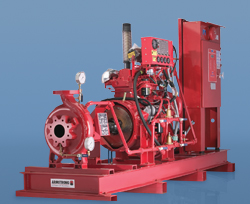
End Suction Fire Pump - Electric Motor Driven*
Supply and install as indicated on plans one (1) fire pump system consisting of:
- FIRE PUMP
One Armstrong, SERIES 40MF, Size _____________ end suction fire pump listed by [Underwriters Laboratories of Canada (ULC)], [Underwriters Laboratories Inc. (UL)] and/or [approved by Factory Mutual (FM)] having a capacity of _______________ USGPM for a pressure boost of _______________ PSIG. Suction pressure ______________ PSIG
Pump casing shall be radially split, top centerline discharge, self venting casing. The pump construction shall be ductile iron, bronze fitted and shall be fitted with packing. The shaft shall be fitted with stainless steel sleeve and be supported by two back to back thrust ball-bearings and one radial roller bearing. The back pullout design shall allow the complete rotating assembly to be removed without disturbing the casing piping connections.
Each stuffing box shall be fitted with a three-piece bronze gland. Stuffing box shall be fitted with a stuffing box extension to facilitate the packing rings removal. Packing rings shall be removable without disturbing wetted
parts or the pump bearings. Water seal rings made from non-corroding material shall be piped to pump volute.
- ELECTRIC MOTOR
The fire pump shall be directly coupled through a UL Listed half-spacer coupling to a horizontal electric motor with a maximum HP of _____________ at __________RPM, _________ VOLT, _______ PHASE _________ CYCLE. Motor shall be UL Listed for fire pump service, open drip proof, standard efficiency with 1.15 service factor.
- MINIMUM FITTINGS
The pump shall be supplied with the following accessories:
- One (1) combination suction gauge 3½” dial type with ¼” cock and lever handle.
- One (1) discharge gauge, 3½” dial type, with ¼” cock and lever handle.
- One (1) casing pressure relief valve.
- OTHER ACCESSORIES
Pump shall be fitted with one (1) eccentric suction reducer and one (1) concentric discharge increaser, as required (by mechanical contractor) to fit NFPA20 recommended piping sizes.
One (1) outside test header shall be supplied with one (1) set of ____ x 2½” hose valves with caps and chains.
- FIRE PUMP CONTROLLER
The fire pump controller shall be specifically approved for fire pump service by [ULC], [UL] and/or [FM]. The controller shall be of the combined manual and automatic stop, ________________ starting method, Model _________as manufactured by ___________. All equipment shall be enclosed in an approved drip proof enclosure. The control equipment shall be completely assembled, wired and tested at point of manufacture prior to shipment.
Circuit breaker shall have an interrupting capacity of ________ kAmps or a withstand rating of ____________ kAmps RMS.
- FIRE PUMP CONTROLLER AND AUTOMATIC TRANSFER SWITCH
COMBINATION
The automatic transfer switch controller combination shall be approved by [UL], [ULC] and/or [FM], Model ________________ as manufactured by ______________. The automatic transfer switch and the pump controller shall each be mounted in separate enclosure, mechanically attached to form one unit and provide for protected interlock wiring.
The automatic transfer switch shall be capable of automatic power transfer from normal to alternate_______________ second utility emergency power source in case of normal supply failure and automatically re-transfer after restoration of normal power conditions.
- JOCKEY PUMP
The jockey pump shall be a vertical multi-stage by Armstrong, Model No. ___________ for a capacity of __________ USGPM and a pressure boost of ____________ PSIG. The jockey pump shall be driven by an [open drip proof] [totally enclosed fan cooled] electric motor of _______HP ________ RPM __________ VOLT ______ PHASE________ CYCLE.
- JOCKEY PUMP CONTROLLER
The jockey pump shall be controlled by an automatic jockey pump controller model ___________ as manufactured by _______________ with full voltage starter.
- MOUNTING AND TESTING
The fire pump shall be hydrostatically tested at twice the maximum working pressure for at least 5 minutes. The fire pump shall be performance tested at rated speed. The fire pump shall furnish remove less than 150% of rated capacity at a pressure not less than 65% of rated head. The shut-off
total head of the fire pump should not exceed 140% of total rated head.
A certified test curve, indicating the flow, head, power and efficiency shall be supplied for the field acceptance test. The fire pump and electric motor shall be base mounted and aligned at the pump manufacturer’s factory. Final alignment shall be made after installation on site.